Designing an Adjustable Joint for Spinal Mobility Support 2026
Project description
I worked on designing and prototyping an adjustable rotational joint for an assistive physical therapy device. Building on the team's existing support system, I researched mechanical solutions, developed and 3D-printed a serrated joint, and tested its movement and locking mechanism. The project is ongoing, with further assembly and testing planned.
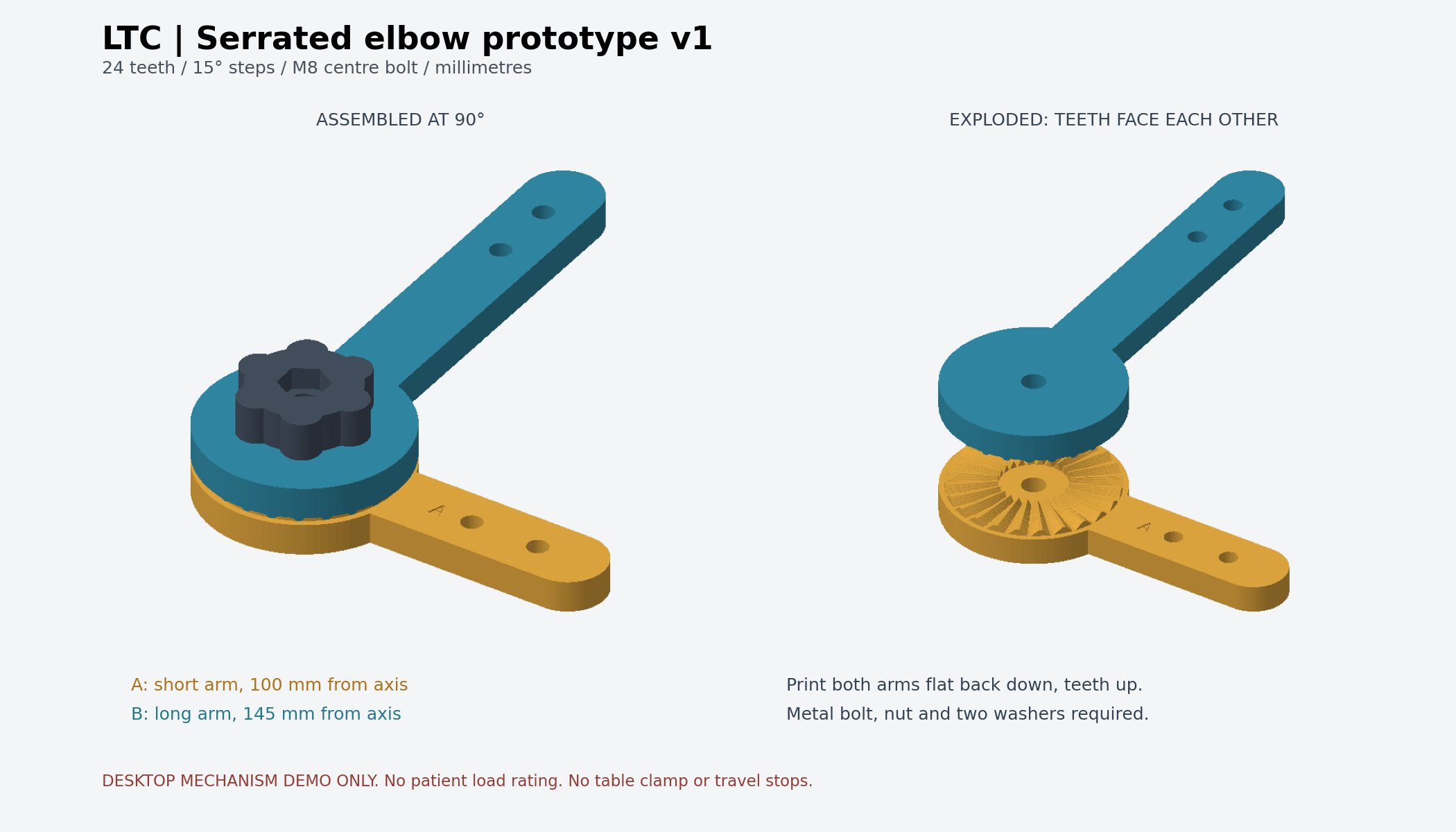
Explore how the serrated joint can be adjusted and secured.
Illustration of intended operation · tabletop prototype, no load rating. Drag to orbit; scroll or pinch to zoom. On the focused model, use arrow keys to orbit and + / − to zoom. Touch gestures over the model control its view. Use Inspect to focus and highlight a component.
Project Background
The project was developed for physical therapist Lawrence Harding. During spinal mobility exercises, a therapist may anchor a support belt with their own body to help a patient remain upright. An adjustable support structure would provide those anchor points and reduce the physical strain on the therapist.
Alisa Mizukami’s earlier documentation records the therapist’s requirements: manageable size and weight for portability, rigid poles, stable positioning, and a pole that can rotate for adjustment. The equipment also needs to fit the therapy environment, including the table height and enough space for the patient to sit upright.
Existing Design & Evolution
The earlier team moved from a chair with one pole to a simpler chair-based design with two poles. Further simplification removed the chair, leaving a pair of supports intended to clamp to the therapy table. These iterations and the requirements research are documented in Alisa Mizukami’s original project documentation.
-
01 / Original chair · Original Physical Design
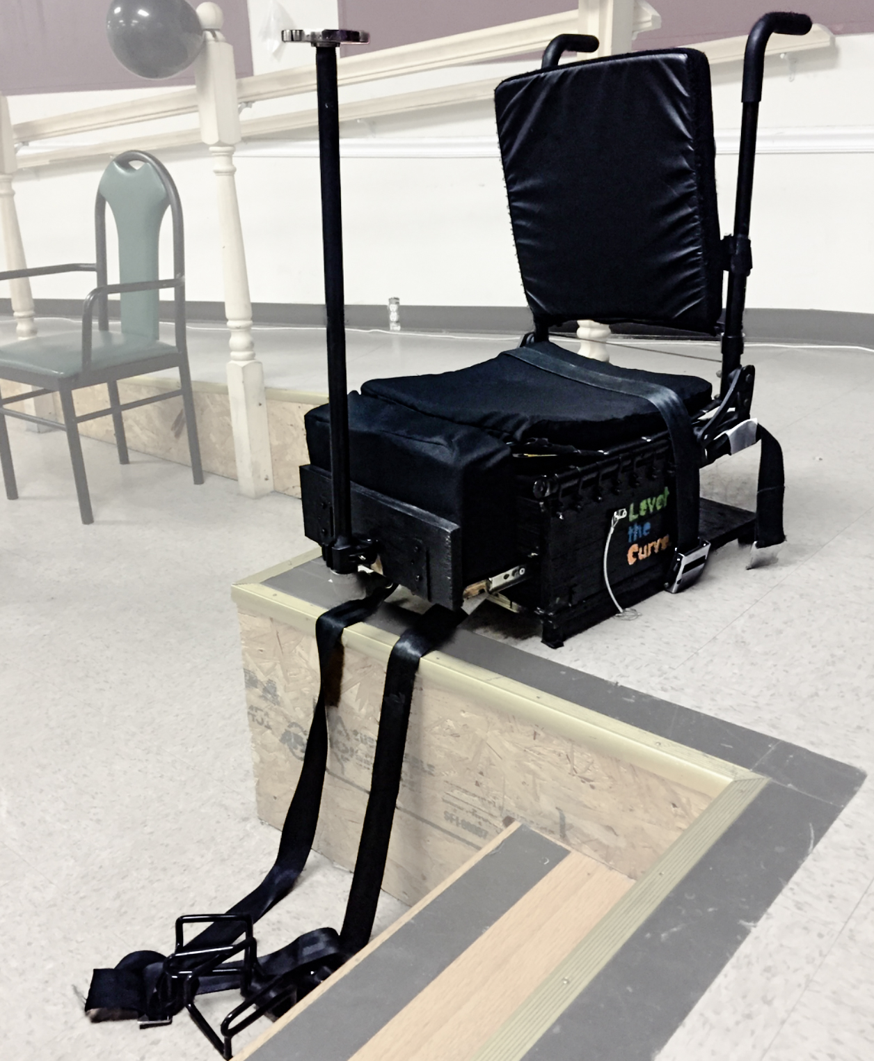
The chair and single pole raised concerns about weight and stability. Original design & documentation:
Alisa Mizukami / Level the Curve -
02 / Simplified chair · Simplified Chair Design
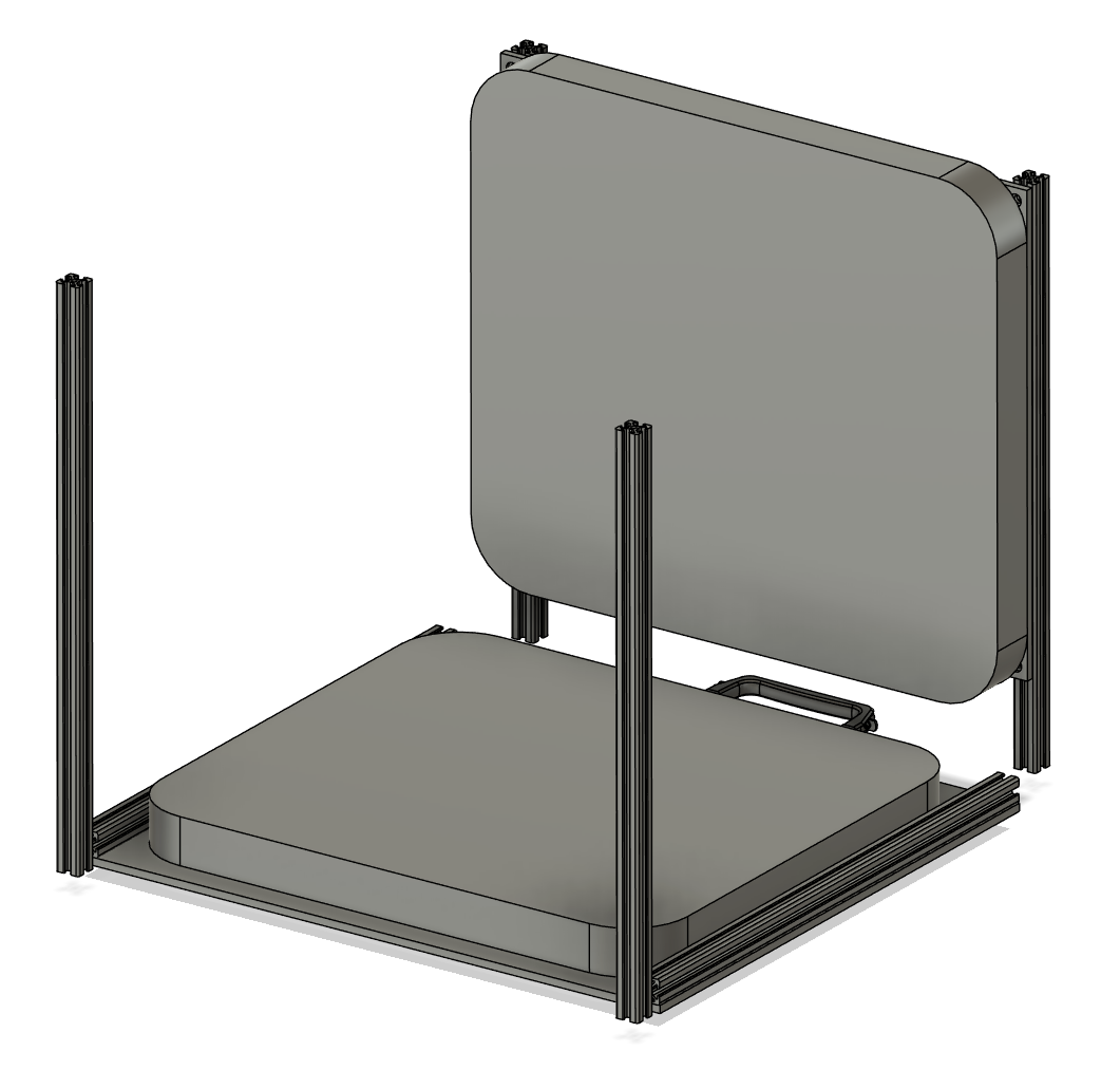
A simplified chair introduced two support poles. Original design & documentation:
Alisa Mizukami / Level the Curve -
03 / Table-mounted support · Therapy Table Attachment Design
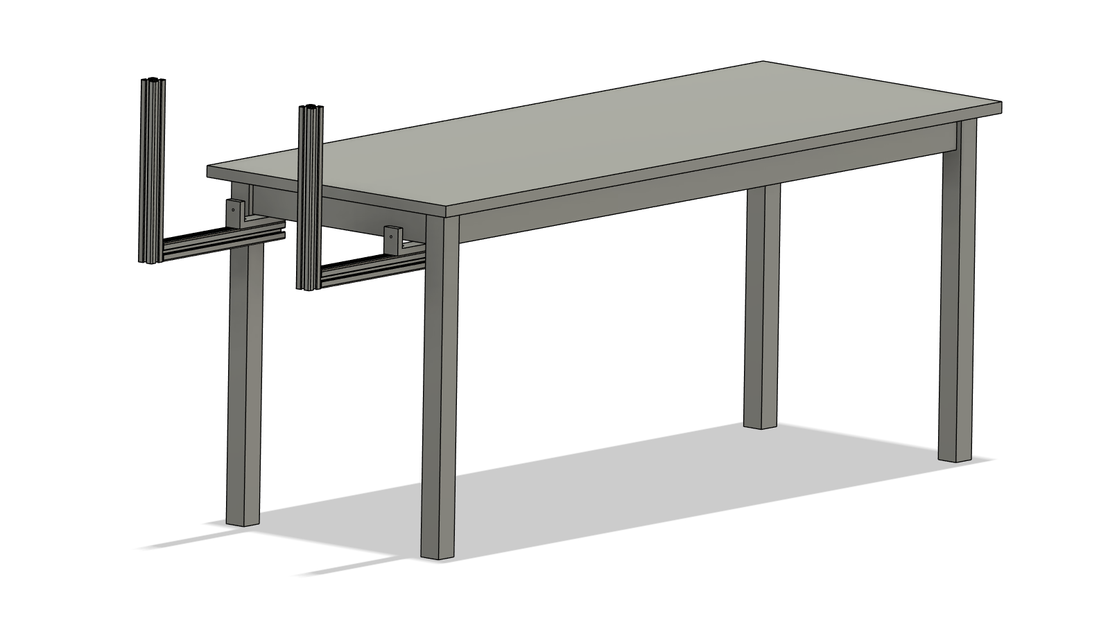
Two poles attach to the therapy table, removing the chair. Original design & documentation:
Alisa Mizukami / Level the Curve
Building on the existing two-pole support structure, I focused on developing a rotational joint that could allow the poles to be repositioned and securely locked.
My Contribution
The earlier documentation identified pole rotation as a feature still to develop. My work investigates that connection through joint research, serrated mechanism exploration, and tabletop prototypes.
Rotational Joint Exploration
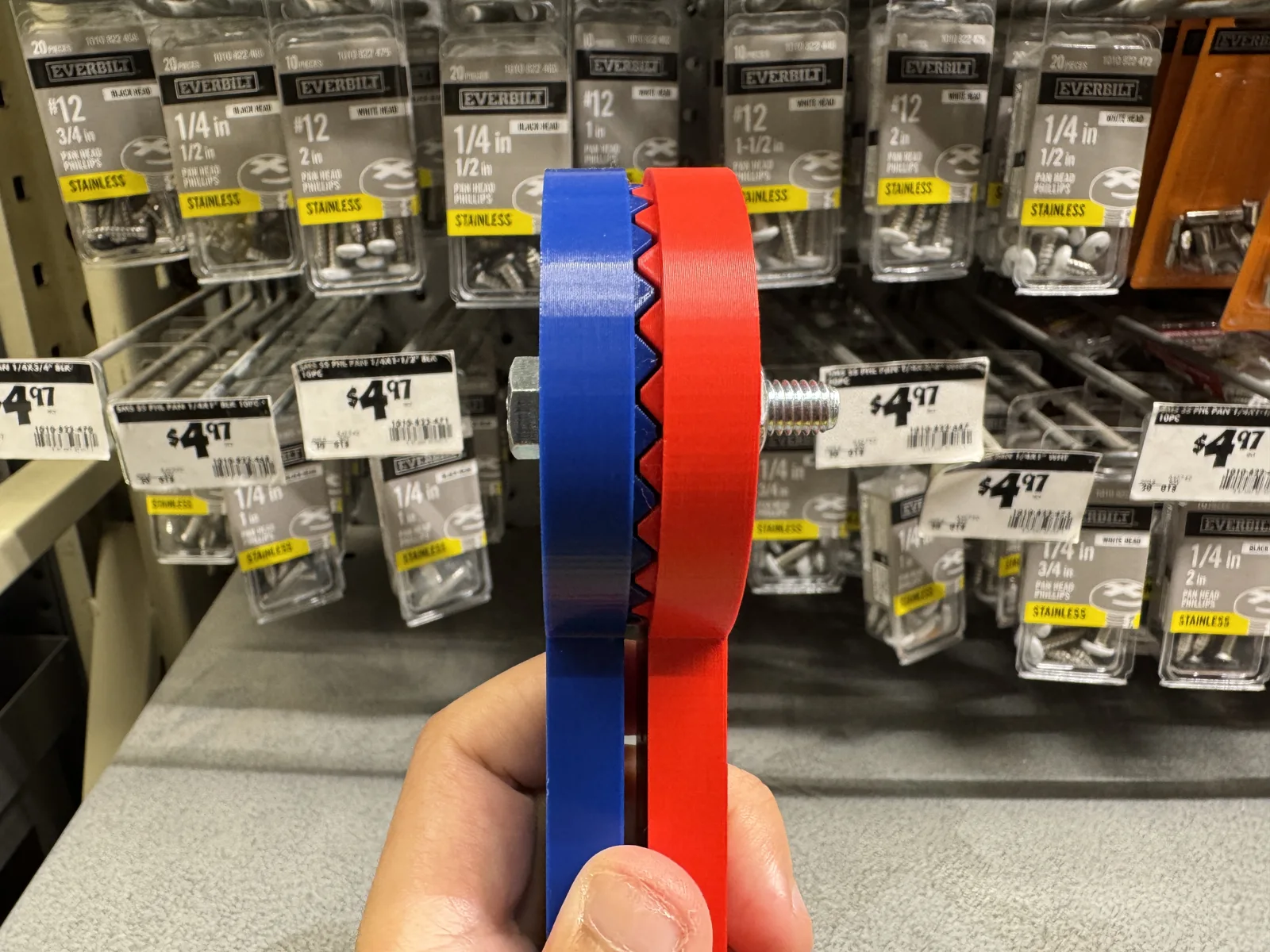
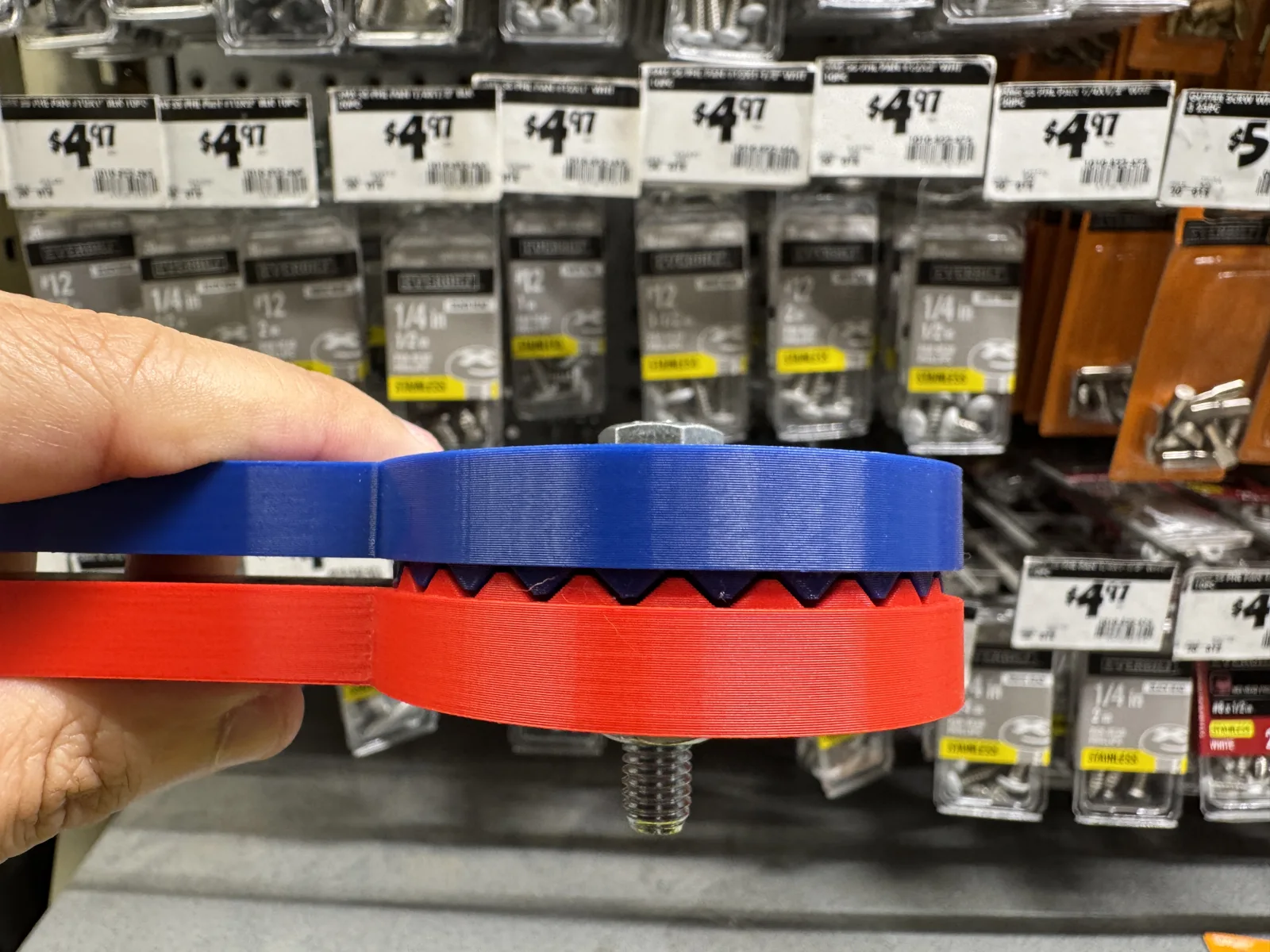
I explored adjustable joints and selected a serrated locking concept for a tabletop prototype. Two complementary tooth profiles provide discrete angular positions; the faces must separate before the angle can change.
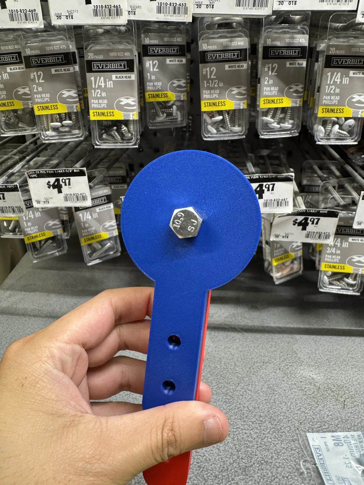
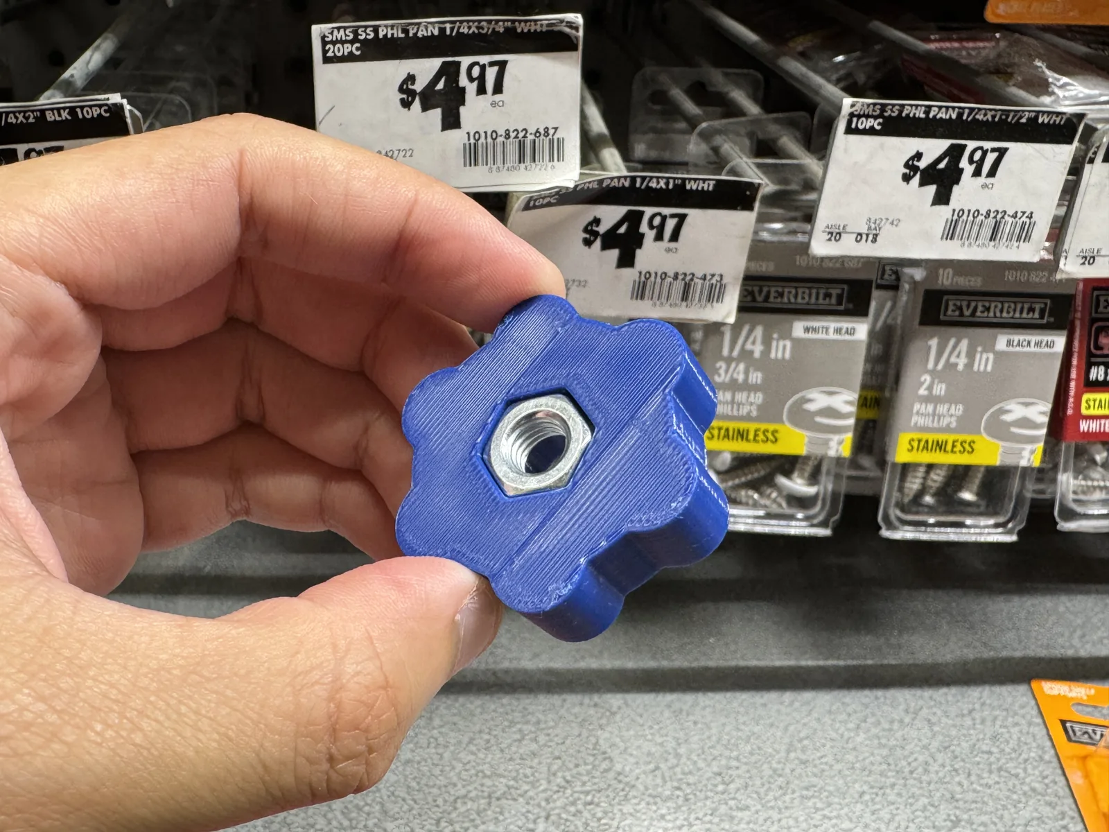
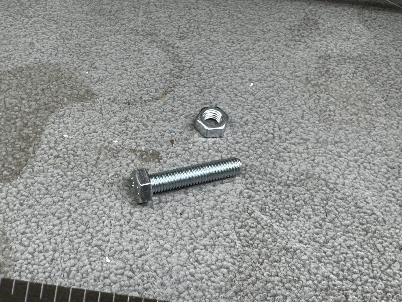
The current geometry uses 24 teeth at 15-degree increments on a 64 mm diameter joint. The short arm extends 100 mm from the pivot, and the long arm extends 145 mm. A central M8 bolt, nut, washers, and separate printed hand knob form the adjustment assembly.
Adjustment sequence: loosen the knob, separate the tooth faces axially, rotate to an indexed position, then reseat the teeth and tighten. The model begins locked at 90°.
The interactive model above uses the original A and B meshes, with B flipped so the tooth faces oppose each other. It illustrates intended operation, rather than simulating friction, deformation, thread engagement, or load capacity.
3D Prototyping
Initial parts have been 3D printed for tabletop mechanism exploration and fit checks. Handling the parts makes the serrated interface, assembly order, and fastener access easier to evaluate than CAD alone.
Current Progress
Initial joint prototypes have been 3D printed, and initial tabletop mechanism exploration and fit checks have been performed. Required assembly materials and hardware are available.
Drilling and integration with the larger support structure are pending. Full assembled-system testing has not yet been completed. This tabletop prototype has no load rating and has not been clinically validated or tested under patient loads.
Next Steps
Reflection
Physical prototyping brings material strength, print tolerances, and assembly access into the design process. A joint that looks aligned in CAD still needs to fit, separate, and reseat reliably when made.
These early checks help identify what to investigate next. They do not yet establish how the joint will behave within the complete support system; that remains part of the integration and testing work ahead.
Project Credits