Week 4: Designing and Prototyping a Rotational Joint
Weekly Goals
- Explore possible rotational joint mechanisms for Lawrence’s Chair.
- Design a joint that allows angle adjustment while maintaining stability.
- Create a 3D model and print the first functional prototype.
- Test the mechanism and identify potential improvements.
Work & Progress
Exploring the Joint Mechanism
Following last week’s meeting with Alisa, I started working on the rotational joint for Lawrence’s Spinal Mobility Chair. The main challenge was finding a way to let the supporting poles rotate while keeping them securely fixed during exercises.
I explored different mechanisms and decided to try a serrated joint: two interlocking toothed surfaces that hold the mechanism at defined angles. This seemed like a useful starting point because it could provide clear locking positions without a complicated mechanism.
The existing support system and earlier chair designs are the work of Alisa and the Level the Curve team. My contribution this week focused on designing and prototyping the joint that could eventually connect to that system.
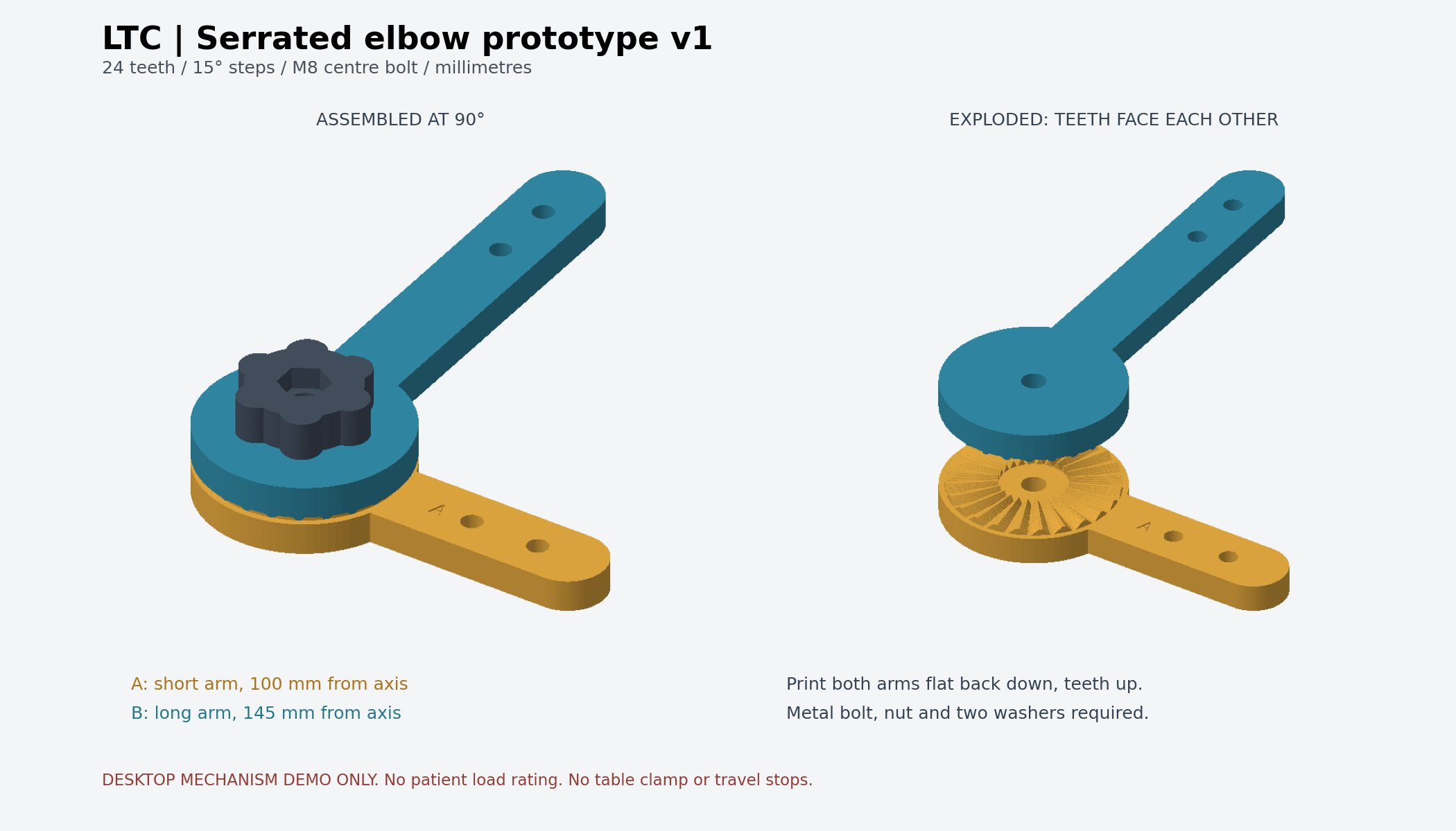
3D Modeling and Prototyping
I created a 3D model with separate joint components that could be assembled using a bolt and nut. The design uses two complementary toothed faces around a central pivot. The modeled interface has 24 teeth, giving it indexed positions in 15-degree increments.
The adjustment sequence helped me think through how the parts needed to work together: loosen the fastener, separate the toothed faces, rotate to a new position, then bring the teeth back together and tighten. Loosening alone would not allow the engaged teeth to turn freely.
After completing the model, I 3D printed the first prototype to see how the mechanism worked physically. I also explored an M8 bolt, nut, and washers to hold the components together. Handling the printed parts made it easier to examine the tooth alignment and assembly than looking at the model alone.
Explore how the serrated joint can be adjusted and secured.
Illustration of intended operation · tabletop prototype, no load rating. Drag to orbit; scroll or pinch to zoom. On the focused model, use arrow keys to orbit and + / − to zoom. Touch gestures over the model control its view. Use Inspect to focus and highlight a component.
Use Play Demo or choose an arm angle to follow the loosen, separate, rotate, reseat, and tighten sequence. Inspect highlights individual components. You can also drag to orbit and scroll or pinch to zoom; keyboard controls are described with the model. This is an illustration of the mechanism, not a recording of the physical test or a simulation of strength. The CAD image and written adjustment sequence remain available if the viewer cannot be used.
Initial Testing
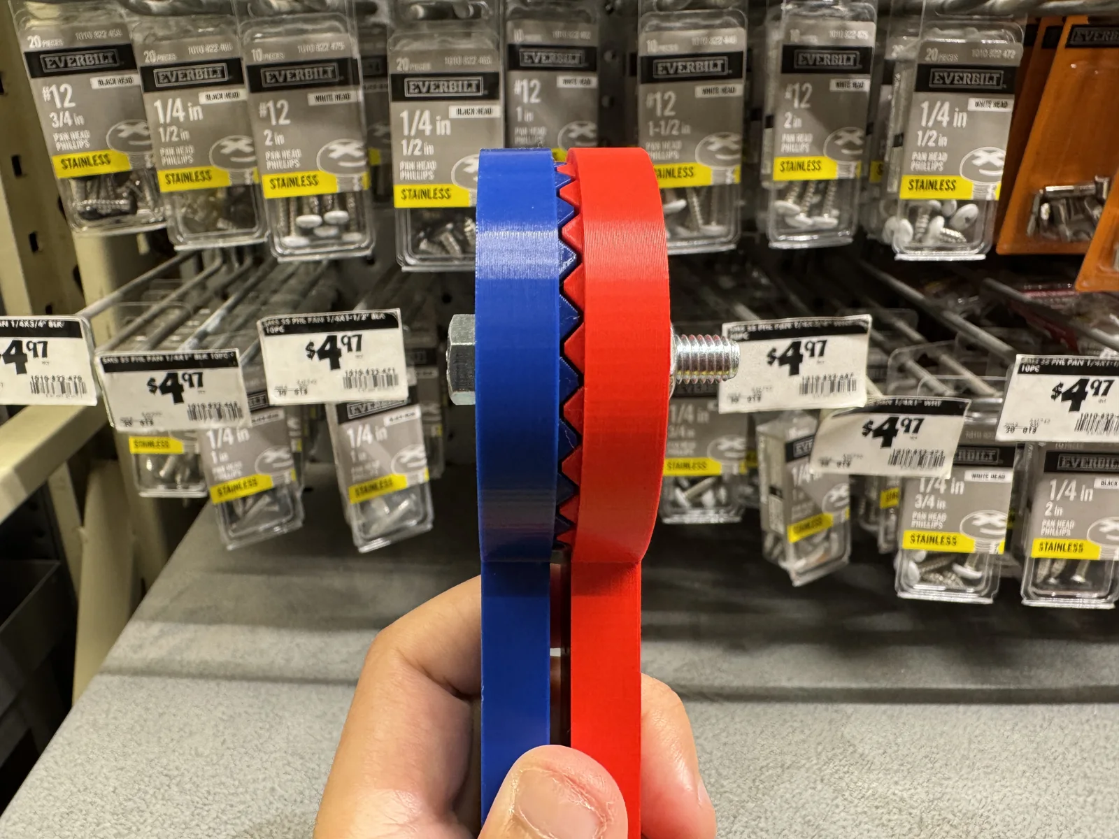
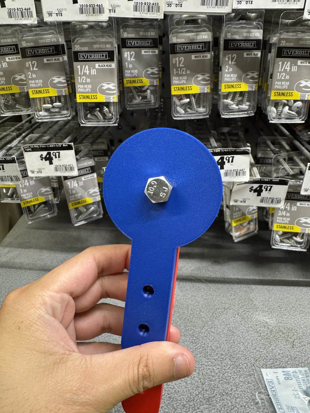
After assembling the prototype, I tested the rotation and locking mechanism by hand. It worked reasonably well for this first check: I could adjust it between different angles and hold it in position when tightened.
This was an early proof of concept. The hand test helped me understand how the printed faces fit and how the mechanism could be adjusted, but it did not establish how much load the joint could withstand. I had not installed it on the chair or tested it with a user.
The next challenge is connecting the joint to the supporting poles and determining which materials would be suitable for actual use. Getting the small mechanism to move and lock was only the beginning of understanding how it would fit into the larger structure.
Challenges / Questions
Although the initial prototype demonstrated the basic mechanism, several design questions remain. A rotating joint also needs to connect to the existing support structure and withstand the forces involved during use. My hand test could not answer those questions.
- How should the joint attach to the supporting poles?
- Are the serrated teeth strong enough to resist rotation under load?
- What material should be used for the final component?
- How much force is needed to tighten and release the locking mechanism?
- Does the joint need additional support or reinforcement?
Next Steps
Reflection
This week was exciting because I started building something for a real assistive technology project. I enjoyed translating a mechanical idea into a physical prototype and seeing whether it worked.
Even though the mechanism is relatively simple, designing something that needs to support physical movement involves more considerations than I initially expected. In CAD, I could focus on the shape and movement. With the printed parts in my hands, I also had to think about fit, assembly, and how someone would actually adjust the joint.
I realized that getting a prototype to work is different from making it safe and reliable for actual use. I’m looking forward to improving the design with Alisa and learning how it fits into the larger system.